Electromyography
General Information
A signal is, by definition, nothing more than the graphical representation of the temporal trend of a physical quantity. In the case of the surface electromyogram (sEMG), this quantity is the potential difference generated by the muscle during its contraction, which produces an electric current in the tissues and a potential difference that is ultimately recorded on the skin. The graphical representation of this is the electromyogram or electromyographic trace or electromyographic signal or sEMG.
When detecting and recording an sEMG signal, two main aspects that influence the fidelity of the recording must be considered: the signal-to-noise ratio and distortion. The first is defined as the ratio between the energy of the useful signal (i.e., the desired signal) and the energy of the noise. The latter consists not only of actual noise (which we could imagine as the background hiss of old 78 RPM records) but also of any other signal that is simply unwanted, such as cardiac signals, signals from other muscles, or signals due to artifacts. This contamination, although often referred to as noise, should more accurately be termed interference, leaving the term noise for purely thermal noise. Distortion, on the other hand, is an alteration of the useful sEMG waveform that manifests mathematically as an undesired variation in the frequency components of the sEMG signal.
The signal-to-noise ratio and distortion are two problems that, by altering the recorded signal representation, can modify or hide the information the sEMG signal is meant to convey.
It is now well known that the amplitude of the sEMG signal is random in nature and can be represented by a Gaussian distribution. Thus, the sEMG signal is not perfectly predictable a priori, not even by analyzing a segment of the trace immediately preceding the one to be predicted. But this is precisely what one would expect from a signal meant to convey information according to Shannon's theory. It follows, again from information theory considerations, that using the Fourier transform on the sEMG signal is entirely inappropriate.
Perhaps at this point, it is worth commenting on why the Fourier transform does not make sense for random or otherwise stochastic signals. In fact, if we admit that a noisy signal should contain all possible frequencies, then we would expect from it a flat Fourier transform, i.e., one containing all frequencies in the spectrum. However, another noisy signal, temporally different from the first, should then have the same Fourier transform. This would lead to the absurd conclusion that two different signals would have the same Fourier transform. So which signal should be reconstructed from the inverse Fourier transform? It follows that the Fourier transform of random signals is not meaningful for their spectral content, and other methods should be used in this regard.
The amplitude of the sEMG (surface EMG) signal depends on many pathophysiological and technical factors. Excluding the latter, we can consider sEMG signals with a maximum amplitude range (dynamic range in amplitude) from 1.5 mV to 10 mV. The frequencies present in the EMG signal range from 0 to 500 Hz, but the diagnostic and clinically useful band ranges from 50 to 150 Hz. Obviously, only signals in this band with an intensity greater than that of noise in the same band are usable.
Characteristics of Noise in the sEMG Signal
Electronic Noise from the Amplifier
An unavoidable source of noise is the one intrinsically present in the electronic circuits used for amplifying and conditioning the sEMG signal. This noise has frequencies ranging from direct current (0 Hz) to tens of kHz. To minimize this noise, state-of-the-art amplifier design techniques and high-quality electronic components must be used.
Electromagnetic Environmental Noise
Another highly annoying source of noise is environmental noise, originating from electromagnetic radiation (radio, television, cell phones, power distribution lines, electrical and electronic devices, etc.) that continuously inundates the human body when it is in modern urban environments. More accurately, this should be referred to as interference. The most significant type is the so-called 50 Hz noise (60 Hz in the American continent and Japan), caused by electromagnetic emissions from power lines. The 50 Hz noise, also known as "mains hum" or "alternating current hum," is particularly disturbing because it often reaches levels that are 100 to 1,000 times higher than the sEMG signal itself. The fight against mains hum is carried out in various ways, including the design of appropriate amplifiers to minimize the recording of 50 Hz noise, proper electrode placement techniques, and, finally, conducting the recording in specially shielded rooms (Faraday cages).
Movement Artifacts
Further disturbances in the faithful recording of an sEMG signal can arise from movement artifacts. This is of particular interest in the recording of surface sEMG because it is evident that movement is inherently generated by the muscle beneath the skin where the electrodes are applied. At least two different types of movement artifacts are described. The first and most obvious is the one that results from a variation in the electrode surface facing the skin. This occurs more easily with large and rigid electrodes rather than small and flexible ones, which can better and more quickly adapt to the changing curvature of the skin over the muscle during contraction. The variation in the electrode surface in contact with the skin produces a sudden change in the electrode's electrical capacitance and, consequently, a variation in the electrode's direct current voltage. The second type is caused by the movement of the cables that connect the electrodes to the amplifier. In this case, the artifact is essentially still due to capacitive variations at the amplifier input, which can be minimized fairly easily with proper design of the amplifier input stages or by shielding the cables. These artifacts typically have a spectrum ranging from 0 to 20 Hz, i.e., outside the useful band for sEMG recording, and can therefore be eliminated by appropriate filtering circuits without significantly altering the useful signal.
Randomness of the EMG Signal
The last and less obvious source of noise in the sEMG signal is the quasi-random nature of the sEMG signal itself. This occurs mainly in the 0 to 20 Hz range of the spectrum and is due to the random frequency of motor unit discharges. Motor units, in fact, have an activation frequency precisely in the 0 to 20 Hz range. The unstable nature of these components of the signal should lead them to be considered noise and, therefore, filtered out. This is normally done. Unfortunately, the reader unfamiliar with signal theory may not fully understand this point. Filtering signals in the 0 to 20 Hz band, where the motor unit firing frequencies are present, might seem counterintuitive, leading to the removal of any informative content from the signal.
But a common-life example might help. Imagine listening to loud rock music from the car stereo of a nearby vehicle, both waiting at a traffic light. What you hear is just a rhythmic succession of drumbeats. But if the driver of the nearby car rolls down the window, you can immediately hear the music. Before the window was lowered, you could perceive the rhythm (low frequency) better than the other sounds (which also followed the rhythm of the music but had a higher frequency content), which the rhythm itself prevented you from understanding. In this example, the window had to be lowered (to allow the music through), whereas in the case of sEMG, the rhythm is filtered out (to better see the signal).
Electrodes
Everyone knows that the recording of biological electrical signals starts with electrodes, but very few realize the real "necessity" of these. Electrodes seem like something inherent in the recording process, and no one really questions their role.
In reality, the problem is quite simple. The electronic circuits for amplifying and recording sEMG signals are essentially made of electrical wires. These wires are obviously metallic (copper), and common electrical charges of a single type flow through them: electrons. Surely everyone knows that electrons flow in electrical wires. However, few people question whether electrons can also flow in the human body. Certainly, cellular potentials, which are the basis for the potential differences detectable on the skin, cause electric currents, i.e., flows of electric charges. But these charges in the body's tissues cannot be electrons. In fact, it is difficult to find free-moving electrons in the human body, as happens in the metallic lattice of a wire. In our body, we have other carriers of electric charge, which are ions. Ions are "pieces" of molecules with a net electric charge different from zero. They are very different from electrons: they can weigh tens or hundreds of thousands of times more and may have multiple charges compared to an electron and even of opposite sign. Unfortunately, they can only flow in an aqueous environment and certainly not in a wire due to their size. So, the situation is as follows: we have an electric current in the metallic wires of the amplifier, just as we have an electric current in the body's tissues, where the carriers are ions. How can we ensure that the electric charge flows in such a "mixed" circuit? How can we ensure that the carriers exchange electric charge? This is precisely the important role of the electrode. Here, a chemical reaction exchanges electric charges between electrons and ions. The only chemical reaction that does this is the one known as redox (oxidation-reduction). Thus, the purpose of the electrodes is to provide a site for a redox reaction that "closes the circuit" and allows electric charges to flow continuously from the body's tissues to the amplifier and vice versa, thus enabling the biopotentials on the skin to be detected and amplified. It all works as if the electric charge travels on one type of transport (electrons) in one environment and another type of transport (ions) in a different environment. We need a sort of "interchange" where the electric charge can be transferred from one medium to another.
This is why electrodes are so important and not just simple and trivial pieces of wire to connect to the skin.
If no one had yet invented an electrode, one could think of making it as follows. It would seem appropriate to make it in two parts: a metallic part to connect to the wire going to the amplifier and a saline part, attached to the former, capable of participating in the redox reaction. Furthermore, it would be important that the electrode's resistance is as low as possible to avoid excessive voltage drop at the electrode, which would result in a smaller value being measured on the trace. Therefore, a low-resistivity metal (and dermatologically suitable) such as silver should be chosen (not gold, as it is too expensive). For the saline part, a silver salt would obviously be chosen. Which one? Since the electrode is placed on the skin, which is in direct communication with the extracellular fluids of the tissues rich in chloride, silver chloride would be chosen. So the electrode would be made as follows: a small metallic silver plate covered with a layer of silver chloride in the area that comes into contact with the skin. To conclude, a sponge soaked in a silver chloride solution in water could be used to ensure the appropriate mobility of ions. It would be wise to keep the entire setup protected from light since light decomposes silver salts, as you might recall from film photography, which has now disappeared. And so we have "invented" a nice electrode. But how does it work?
The redox reaction that occurs between the electrode and the skin is the following:

and everything seems to work well. In particular, since the reaction is reversible, there is the possibility of current flowing in both directions with the same redox reaction. The electrode is said to be reversible. But what happens if the current flows in only one direction, as in long-duration electromyographic measurements? In this case, the electrode could "wear out," meaning that the chloride layer could dissolve entirely, and the metallic silver would come into direct contact with the skin. Thus, the electrode is said to be consumable. A silver/silver-chloride electrode is both reversible and consumable. The depletion of the electrode is not a positive outcome. To make a measurement with the amplifier, at least two electrodes are needed. Each of them will probably "see" a different concentration of chloride ions in the area where it is placed. This will cause each electrode to generate its own half-cell potential (Nernst equation) different from the other. This potential is also known as the liquid junction potential. Since the two potentials are different, they will not cancel each other out, and thus the measured value will be the muscle potential added to the difference in the half-cell potentials of the electrodes. The muscle electrical potential has values well below a millivolt, while the liquid junction potential has values on the order of volts. This fact makes the measurement somewhat complicated, but it is still possible to manage this phenomenon and obtain good recordings. At least until the electrode is in good condition! Once the chloride is completely depleted, the half-cell potential becomes unpredictable and erratic, depending on other ions present in the area, as well as impurities in the silver. It will be very difficult for the electromyographic amplifier to compensate and overcome this effect. At this point, it is said that the electrode has become polarized and can be discarded without regret.
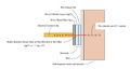
Figure 1: Schematic diagram of the transformation of an ion current (negatively charged) into an electron current (negatively charged) through the exploitation of the redox reaction made possible by the presence of the electrode.

It would be nice, then, to invent an inexhaustible electrode. One could be made with a plate of metallic platinum. Platinum catalyzes the electrolysis of water (we are obviously in an aqueous environment), and we have the following reaction:

However, this time it is a non-reversible reaction, so if the current direction is reversed, a different reaction occurs:

Thus, we have an inexhaustible electrode (platinum catalyzes the reaction but does not chemically participate in it, so it does not wear out), but it is irreversible. The production of gas (gaseous hydrogen or gaseous oxygen) during the electrolysis reaction is quite inconvenient because the gas tends to insulate the electrode from the skin, making this type of electrode not particularly useful.
Although there are at least two or three other types of electrodes for electromyography, the Ag/AgCl electrode is the most commonly used and is now sold for just a few dozen cents each.
Historically, an interesting electrode is worth mentioning: the "spray-on" electrode, developed by NASA for monitoring the electrocardiograms of the first astronauts. The spray-on electrode was made by spraying colloidal graphite (carbon powder) onto the skin, effectively painting it. The conductive graphite created an intimate contact with the skin, and a normal metal wire could simply be placed on the "black patch." Today, the spray-on electrode is almost no longer used.
Electrical Characteristics of Amplifiers
The design of the amplifier is the most critical part of the electronic devices used to record the sEMG signal. The fidelity of the sEMG signal detected by the electrodes and the amplifier influences all subsequent processing and presentation stages, and nothing can be done to restore a signal that has been incorrectly or distortedly acquired. A number of characteristics are important for this purpose; they are often advertised by manufacturers of the equipment, but much more rarely understood by the users.
Differential Amplification and CMRR

As mentioned earlier, the issue of 50 Hz noise is potentially a rather difficult inconvenience to eliminate. The universally adopted technique to address this starts from the concept that such noise should be the same at all points on the body, while the bioelectric signal to be acquired in the same points must be different. Therefore, a differential amplifier is used. This can be thought of as consisting of two identical amplifiers whose output signals are subtracted from each other by an appropriate subtraction module. If the disturbing signal is the same at both inputs, it will be canceled at the output by the subtractor, while the useful signal, which is different at both inputs, will be amplified in a so-called differential manner. The disturbing signal that is the same at both inputs is also called a "common-mode" signal. Any signal generated far from the body has a high chance of being seen as a common-mode signal, while all signals generated near or inside the body will be "differential" signals. Therefore, noise generated by electromagnetic induction from power lines at 50 Hz will be actively canceled from the final recording of the sEMG signal. Clearly, this explanation requires the availability of highly accurate subtractors, since the common-mode signal can be thousands of times larger than the differential signal. In practice, perfect subtraction can never be achieved, only approximated to varying degrees of quality. The accuracy with which the subtractor performs the difference of the signals from the two inputs can be numerically expressed by the CMRR parameter of the amplifier. The CMRR is the "common-mode rejection ratio" and represents the ratio between the amplification of the differential signal and the amplification of the common-mode signal (which is very low and tends to zero due to the subtractor). Therefore, a perfect, ideal subtractor will have a CMRR equal to infinity. In practice, CMRR values range from 90 to 120 dB (the measurement is expressed in dB as 20 times the base-10 logarithm of the above ratio).[1][2]
As strange as it may seem, there are at least three reasons why it is not practical to have a very high CMRR: the first is that amplifiers with extremely high CMRR tend to be excessively expensive; the second is that such amplifiers are increasingly less stable and reliable in the long term as the CMRR value increases; and the third is that common-mode signals are not necessarily common-mode in an absolute sense, as they may have small phase or amplitude variations that undermine the best CMRR. In addition, alterations or asymmetries in the electrodes can have dramatic effects in lowering the overall CMRR of an amplifier that is otherwise of good quality. (Fig. 2)
Input Impedance
The impedance of a circuit in which alternating currents flow (i.e., currents that do not always have the same direction and intensity over time) is the equivalent of resistance for direct current circuits. The difference is that impedance varies with the frequency of the currents, and thus a filtering effect is generally obtained, whereby certain signals at a particular frequency may be recorded with higher or lower intensity depending on the impedance of the circuits (typically electrodes and cables) through which they pass.
Specifically, to avoid unwanted attenuation and distortion, the impedance of the skin and electrode must be as low as possible, while the input impedance of the amplifier must be as high as possible, so that the current drawn from the biological generator that flows through the external circuits is minimized. Modern electronic circuits allow the creation of amplifiers with input impedances reaching up to 1015 ohms, with input capacitance on the order of a few picofarads. Considering that the voltage from the surface sEMG signal is on the order of 10 mV, with an impedance of 1015 ohms, the current in the electrodes and amplifier is minuscule, amounting to only a few thousand electrons (!) per second. However, it is not just the absolute value of the input current into the amplifier that matters: the balance of the currents in all the electrode circuits is also highly important. This requires not only careful amplifier design but also precise measurement techniques.
Design and Use of "Active Electrodes"
The requirement for a very high input impedance of amplifiers introduces a problem known as capacitive coupling at the inputs.
Indeed, with a very high input impedance, even the small capacitance between the electrode cables and the electrical distribution wires of the power grid can no longer be ignored. The solution to this issue involves reducing the length of the electrode cables or moving the amplifier as close as possible to the electrodes. So close, in fact, that it is incorporated into the electrode itself, thus creating an "active electrode." The already pre-amplified signal is then sent to the instrument through low-impedance cables, completely immune to the problem mentioned above.
Filtering
Even with the aforementioned considerations and the most scrupulous methods, the sEMG signal can still be contaminated by unwanted signals that can be eliminated using various filtering techniques. These techniques are based on circuits (or software programs in the case of digital filters) that allow the useful signals to pass through almost unchanged while strongly attenuating noise or other unwanted signals. For the sEMG signal, filters can pass signals in the band from 20 to 500 Hz, with out-of-band attenuation decreasing by 12 dB/octave, meaning a 12 dB reduction for every doubling or halving of the frequency beyond the minimum and maximum limits.
Stability of the Electrodes
Electrode stability refers to mechanical, electrical, and electrochemical stability. Mechanical stability has already been discussed. Electrical and electrochemical stability are related to the progress of the redox reaction that occurs at the electrode's contact with the skin and the skin's electrical characteristics. Problems can usually arise from abnormal changes in the hydration state of the electrode, such as drying out or excessive moisture due to sweat, for example.[3]
Geometry and Placement of Electrodes
Throughout the history of electromyographic recordings, the shape and placement of the electrode surface have never received much attention. This is likely because a qualitative evaluation of the signal was given more emphasis, and this approach has persisted even in the approximate methodologies that have been used. To this day, the study of the sEMG signal has not achieved a stable "quantitative" reputation in the sense of being widely accepted. This is even more curious when considering that another specific "sEMG signal," that of the cardiac muscle or electrocardiogram (ECG), has long been established as an examination of undeniable clinical importance.
Moreover, signal processing through computer methods now presents significant challenges in terms of quantifying or at least objectifying electromyographic measurement.
Distance Between Electrodes
The distance between the electrodes greatly influences the bandwidth, amplitude, and phase of the sEMG signal. This means that the distance between the electrodes significantly affects the signal's shape, thus producing a kind of distortion. The fact that it also influences the phase tells us that time measurements (delays, latencies, periods) derived from the sEMG signal in reference to external stimulation events also depend on this. Ultimately, the distance between electrodes, although often underestimated in practice, is a fundamental parameter for performing quantitative sEMG measurements, i.e., reproducible and therefore comparable.[4]
It is therefore clear that it would be highly preferable for the set of electrodes to be mounted on a rigid support so that the arrangement of the electrodes cannot vary in subsequent installations on the same subject or on different subjects (under comparable anatomical conditions). The distance between electrodes also depends on their size and the need to make measurements on small muscles without interference from sEMG signals from nearby muscles. A minimum distance of 1 cm is often considered adequate, but there are applications where the distance is even smaller.[5]
Small distances are generally avoided because it is believed that the signals may be altered by local conditions. Sweat is considered a hazard in these cases because it tends to "short-circuit" the electrodes on the skin. This is a controversial issue and is not considered valid by the author. In fact, beneath the skin, there is a natural "short-circuit" made up of the extracellular fluids of the subcutaneous tissue and dermis. An external "short-circuit," with an impedance similar to that of the interior, should therefore not alter the measurement. Some argue that constructing amplifiers with extremely high input impedance would be pointless in this way. However, the "short-circuit" would occur between the electrodes, not between the wires leading from the electrode to the amplifier, and the high input impedance of the amplifier continues to be relevant in counteracting the electrode impedance itself. Some also argue that, for the same reason, it would not be possible to make sEMG measurements in water, while the author has regularly developed radiotransmitting electromyographic systems for swimmers. Moreover, no one has ever questioned biopotential measurements, such as sECG, taken in "humid" environments, such as intraesophageal ECG or even invasive biopotential measurements.[6]
Size and Shape of Electrodes
It is certain that the larger the size of the electrode, the higher the level of the recorded signal and the lower the noise. However, a large electrode has the disadvantage of acquiring signals from different muscles or from parts of the muscle that are not of interest; specifically, spatial selectivity is lost. Therefore, an electrode is needed that captures the maximum number of muscle fibers from a restricted area with low noise. It is evident that these requirements are in conflict, and some compromise must be reached.
In addition to the conventional circular shape, other configurations such as array or bar electrodes are now being used, each with relative advantages and disadvantages. The "correct" shape remains an achievement reached through more or less heuristic attempts and depends on the operator.
Localization and Positioning of Electrodes
Electrodes should be placed between a motor point of muscle innervation and the tendon or between two motor points, and oriented along the muscle belly's longitudinal median line. Thus, the longitudinal axis of the electrodes should be aligned parallel to the length of the muscle fibers.
Electrodes should not be placed near the tendon. In such locations, muscle fibers are thin and sparse, and there is also the risk of "picking up" sEMG signals from other muscles (e.g., agonists).
Similarly, electrodes should not be placed on the motor point, although this is a difficult preconception to overcome. The motor point is the point on the muscle (and its equivalent projection on the skin) where the injection of a minimal current causes a well-defined contraction of the muscle itself. Usually, but not always, this point corresponds to the part of the muscle where innervation occurs and where the highest density of neurons is found.
However, from the standpoint of signal stability, measuring with two electrodes near the motor point is the worst situation to be in. From this region, the activation potentials of the muscle fibers propagate proximally and distally, and the relative positive and negative phases either sum or cancel out on the electrodes, producing a very distorted signal characterized by sharp, sudden spikes due to the random situation. Stability is particularly compromised here because it is evident that small movements of the electrode will cause huge variations in the trace and its frequency and phase characteristics.
It is also not advisable to place electrodes at the muscle's extremes (one on the origin and one on the insertion). In this case, too large a volume of tissue is under observation, and signals from muscles that are not of interest are easily captured.
Orientation Relative to Muscle Fibers
It is therefore clear that the longitudinal axis of the electrode configuration should be parallel to the muscle fibers. In this way, most of the fibers present in that area will be recorded along with the signal's spectral characteristics. This is important because the independence of the signal's spectrum from any trigonometric factors will prevent erroneous estimation of conduction velocity. For similar reasons, delay, period, and latency measurements will be more accurate and repeatable.
The "Mysterious" Reference Electrode
The main issue with the reference electrode is that in most electromyographic equipment, it is called "ground" or "earth." The operator, usually unfamiliar with electronic or bioelectric aspects, perceives it as something related to patient safety or noise reduction (e.g., 50 Hz noise that would be "discharged" to "ground," as one would do with a household appliance). This is absolutely false and leads to great failures and wasted time.
The need for and importance of using a differential amplifier to record bioelectric signals has already been explained. It was said that a differential amplifier is essentially composed of two amplifiers that amplify the potential at two points, and the difference is taken instant by instant. Each amplifier will have two electrodes between which the potential difference is measured. Consider placing one electrode near the right temporalis muscle of the patient in Figure 1 and another electrode somewhere else on the skull. A recording of the potential difference between the muscle and the reference electrode will be obtained. If a second amplifier is used, with the electrodes placed between another area of the muscle and the same reference electrode, or another reference placed on the ear tragus, as in Figure 1, another recording of the potential difference between the masseter and the tragus will be obtained. The difference between the two (i.e., the difference of the two potential differences) will be the potential difference between the two muscle areas! It sounds like a tongue twister, but let’s do the math to clarify the concept.
Let be the potential difference between electrode and the reference electrode ; similarly, will be for the other electrode. The value of will be the sum of two components: the biological potential difference in that area () plus the common-mode signal, for example, the 50 Hz signal (). Similarly for . In formula:


We know that the differential amplifier amplifies the difference between the inputs, and thus the output of the differential amplifier, after an amplification of 1 (for simplicity), will be:


Simplifying the algebra:

The same exact procedure applies to the masseter muscle (D, E, R).
This is precisely the potential difference between the two muscle areas under electrodes A and B. As can be seen from the formula, the common-mode signal has disappeared in the final equation, meaning it could have been anything, assuming that the common-mode voltage between either of the two electrodes A or B and the reference electrode is equal.

Indeed, because of the difference between the signals of the two amplifiers in the differential amplifier, it is not necessary to place the third electrode exactly on the leg. It could be placed anywhere. Not surprisingly, this electrode is often called the "indifferent" electrode because it can be "indifferently" placed anywhere on the body surface. It is also called "ground" or "earth" or "reference," but in the sense of being the reference for the differential amplifier. It is more of a technical, electronic issue than a bioelectric one. In electrocardiographic (ECG) recordings, the indifferent electrode is the "right leg" electrode.[7]
In practice, the indifferent electrode should be placed far from the recording site. An area where it can be well connected with low impedance contact, perhaps over a bony prominence (in electroencephalography, the mastoid process is used). For the same reason, it should preferably be a large electrode.
It is important to remember that it is not a "ground" electrode in the electrician's sense. It is often also identified as "isolated ground" to indicate that it is a reference for the amplifier, not the safety or shielding ground of the machine or machines in the recording area. Otherwise, the patient would be at risk of electrocution, as the patient must always remain isolated from everything to ensure safety, much like a pigeon on a high-voltage wire.
Electrical Safety of Equipment
A failure in a device powered by electricity that has direct galvanic contact with the patient's skin can pose a health risk, as a potentially dangerous current could flow through the subject, who typically cannot defend themselves.
This problem is usually non-existent in battery-powered low-voltage equipment (from 3 to 15 V), but it becomes important in mains-powered equipment. While absolute safety cannot be achieved in all possible cases, isolation between the circuits connected to the patient (low-voltage powered) and the remaining parts of the device is usually considered adequate. This can be achieved through magnetic coupling (isolation transformer) or optical coupling (optoisolator or photocoupler). The isolation transformer is generally the simplest method from a technical perspective, but it can also be the source of the most problems regarding recording fidelity. In both cases, isolating the patient from the rest of the circuit also minimizes induced 50 Hz noise.
The safety levels of sEMG equipment are regulated by specific harmonized standards at the European level, which are used to assess the quality of the instruments. A "minimum" level of safety must be present in the equipment according to various European directives. Only if this minimum level of safety is met can the equipment be marked with the CE (Conformité Européenne) mark, allowing its commercial circulation within all EU states.
Processing of sEMG Signals
For a long time, the most common form of processing the sEMG signal was to integrate the rectified waveform. This is done by rectifying the signal, i.e., making the negative deflections of the trace positive using appropriate electronic circuits. The resulting signal is then integrated, meaning it is passed through a low-pass filter that outputs a much smoother signal, averaging all the peaks of the original rectified signal instant by instant.
This type of processing was particularly popular because it was easy to implement with simple electronic circuits long before the advent of computers and digital signal processing.
Today, more appropriately, especially thanks to the use of digital signal processing, the root mean square (RMS) value of the signal is used.[8] In this case, each signal value is squared and then averaged over time. In this way, the negative values of the signal become positive since squaring a negative value gives a positive result. Another type of processing is the one that provides the mean rectified value. This, along with integrated rectification, is an approximate measure of the area under the sEMG signal, but neither has a precise physical, physiological, or clinical meaning. The RMS value, on the other hand, is a measure of signal power and therefore has a more relevant clinical meaning. For this reason, it is increasingly used today.
In addition to these amplitude-related measurements, it is essential to remember the time measurements related to the onset of various sEMG signals. These times can be correlated with an external mechanical or electrical stimulus, as in the study of reflexes, or with movements or forces applied or exerted by one or more skeletal segments. These measurements are of interest in biomechanical studies.
- ↑ Wang Yang. A New Type of Right-leg-drive Circuit ECG Amplifier Using New Operational Amplifier. Journal of Physics: Conference Series 1846 (2021) 012034 doi:10.1088/1742-6596/1846/1/012034
- ↑ Bruce B. Winter; John G. Webster. Driven-right-leg circuit design. Journals & Magazines IEEE Transactions on Biomedic..Volume: BME-30 Issue: 1
- ↑ J.V. Basmajian and C.J. De Luca, Muscles Alive. Their Functions Revealed by Electromyography, fifth edition (Williams and Wilkins, Baltimore, 1985).
- ↑ A C MettingVanRijn 1, A Peper, C A Grimbergen. Amplifiers for bioelectric events: a design with a minimal number of parts. Med Biol Eng Comput1994 May;32(3):305-10. doi: 10.1007/BF02512527.
- ↑ E M Spinelli 1, N H Martínez, M A Mayosky. A transconductance driven-right-leg circuit . IEEE Trans Biomed Eng1999 Dec;46(12):1466-70. doi: 10.1109/10.804574.
- ↑ Palla´s-Areny R, Webster JG. AC amplifiers. In: Analog signal processing. (Wiley, New York, 1999:97–109).
- ↑ M J Burke 1, D T Gleeson. A micropower dry-electrode ECG preamplifier . IEEE Trans Biomed Eng. 2000 Feb;47(2):155-62. doi: 10.1109/10.821734.
- ↑ E M Spinelli 1, N H Martinez, M A Mayosky. A single supply biopotential amplifier. Med Eng Phys. 2001 Apr;23(3):235-8. doi: 10.1016/s1350-4533(01)00040-6.